Car Parasitic Drain Testing (Series Edition): Measuring Parasitic Draw with a Tester Switch
Does your car battery go dead after sitting parked for just a few days? You are likely dealing with parasitic drain (quiescent draw / battery leak).
In conventional diagnostics, measuring current in series with a multimeter requires detaching the negative battery terminal. However, the moment of disconnection resets trip computers and radio settings, and the sudden current surge upon reconnection can instantly blow your multimeter’s 10A fuse.
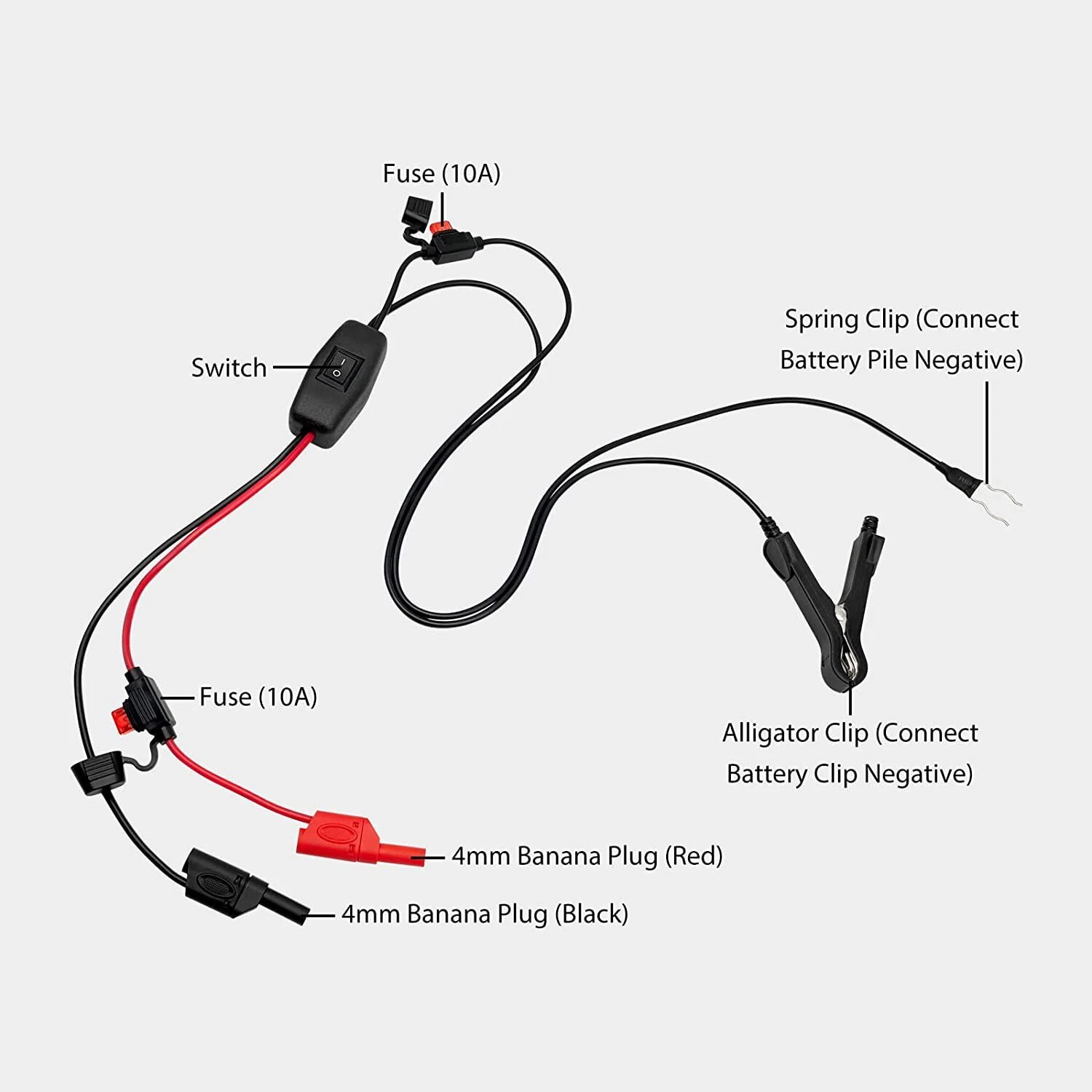
The primary purpose of a Parasitic Drain Tester (Bypass Switch) is to safely insert your multimeter in series without cutting vehicle power, preventing inrush surges from destroying meters while stopping computers from waking up or losing memory.
💡 Series Navigation:
If you have a DC microamp clamp meter and prefer a completely non-invasive, zero-tool measurement method, check out our companion guide:
👉 Car Parasitic Drain Testing (Clamp Meter Edition): Measuring Parasitic Draw with a DC Clamp Meter
What Is a Parasitic Drain Tester?
This specialized automotive diagnostic tool features:
- Dual-Path Seamless Toggle Switch:
- ON (I / Closed): Internal bypass conducts 100% of the current through the tool body. Multimeter reads 0A, safely absorbing heavy pre-sleep currents.
- OFF (O / Open): The internal bypass opens, forcing all return current through the multimeter banana plugs for accurate milliamp (mA) measurement.
- Dedicated Battery Clamps: Features a U-shaped spring clip (slips directly onto the negative battery post before loosening cables) and a fully insulated alligator clip (grips the original cable clamp).
- Dual 10A Blade Fuses: Replaceable external 10A fuses provide dual-layer protection against accidental overcurrent.
- Stackable 4mm Pure Copper Banana Plugs: Plugs straight into standard multimeter jacks.
[!CAUTION]
⚠️ Short Circuit & Blown Meter Warning
Turn off the engine and remove the keys before testing. NEVER start the engine or turn the ignition to ACC/ON during testing!
Do not operate heavy loads (headlights, power seats, A/C blower, heated seats), or current will spike to tens or hundreds of amps, instantly destroying the tester fuses and meter.
Standard Operating Procedure (SOP)
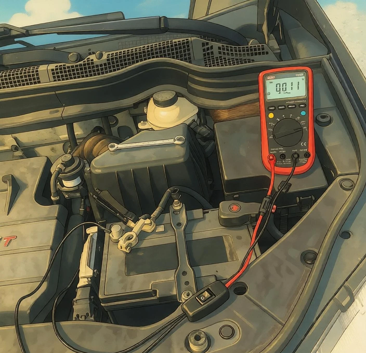
Step 1: Vehicle Preparation & Hood Latch Disguise
- Turn off the engine, shut off all interior lights, and remove the ignition key.
- Roll down all four windows completely (crucial: avoids accidental lockouts).
- Open the hood. Use a screwdriver to push the hood latch mechanism downward into the “closed/locked” position. This tricks the anti-theft module into registering the hood as fully closed.
Step 2: Confirm Tester Switch is Set to ON (Closed / Bypass)
Before connecting any wiring, set the tester switch to ON (I / Closed). The tool is now internally shorted, directing current safely through its heavy-gauge wiring rather than the multimeter.
Step 3: Install Clamps onto the Negative Battery Terminal
- Securely clamp the U-shaped spring clip onto the metal base of the battery negative post.
- Firmly attach the insulated alligator clip to the original negative cable terminal.
Step 4: Connect the Multimeter
- Plug the tester’s black 4mm banana plug into the multimeter COM port.
- Plug the red 4mm banana plug into the 10A / 20A high-current port (never start in the mA port).
- Turn the dial to DC Amps (DC A).
Step 5: Loosen and Isolate the Original Negative Terminal
- Use an M10 wrench to loosen the original battery negative clamp nut.
- Carefully lift the original cable clamp off the battery post (power remains continuous via the tester).
- Slide a piece of thick cardboard or plastic between the cable clamp and battery post to prevent accidental metal contact.
Step 6: Lock the Car & Wait for Deep Sleep (15 - 45 Minutes)
- Close all vehicle doors and press the remote key to lock the car.
- Move smart keys (Keyless) at least 5 meters away from the car to prevent proximity polling.
- Wait 15 to 45 minutes for all onboard modules (BCM, ECU, gateway) to finish self-diagnostics and enter deep sleep mode.
Step 7: Flip Switch to OFF and Read Parasitic Draw
- Ensure the multimeter is still powered on.
- Flip the tester switch to OFF (O / Open).
- The bypass is broken, routing all current through the multimeter. Read the steady parasitic draw on the display.
[!TIP] Changing to High-Resolution Range (mA Setting):
If the draw is low and you want to switch to the mA range for decimal precision, always flip the tester switch back to ON (Closed) before switching meter dials or moving test leads, then flip back to OFF. Never change meter ranges while the switch is in the OFF position!
| Reading (DC Amps) | Status | Assessment & Action |
|---|---|---|
| 20mA - 60mA (0.02A - 0.06A) | ✅ Normal | Standard anti-theft and clock memory draw; battery will last weeks. |
| 60mA - 80mA (0.06A - 0.08A) | ⚠️ Slightly High | Inspect accessories (e.g., parking mode dashcam in standby). |
| > 80mA (or hundreds of mA) | ❌ Excessive Drain | Serious parasitic leak. Will drain battery in days; start pulling fuses! |
Fuse-Pulling Diagnostic Technique
If your parasitic draw exceeds 60mA, leave the tester in OFF and locate the leak:
- Locate Fuse Boxes: Engine bay, under-dash, or trunk fuse panels.
- Pull One Fuse at a Time: Use a fuse puller to extract one fuse at a time while watching the meter.
- Isolate the Culprit:
- If the reading does not change, reinstall that fuse and move to the next.
- When pulling a specific fuse causes the reading to drop sharply under 50mA, that circuit is your leak source!
- Common Culprits:
- Hardwired dashcam buck converters (defective low-voltage cutoff).
- Aftermarket Android head units or amplifiers (remote ACC wire staying powered).
- Faulty door latch microswitches (preventing body computer sleep).
- Glove box, visor vanity, or trunk lights staying on.
Safe Restoration Procedure (SOP)
Always restore the connection in strict order to avoid disconnection sparks or ECU memory loss:
- Flip Back to ON: Switch the tester to ON (I / Closed).
- Unplug Multimeter: Disconnect the 4mm banana plugs from the meter.
- Reinstall Negative Terminal: Remove the cardboard barrier, seat the original cable clamp firmly onto the battery post, and tighten the nut with an M10 wrench.
- Remove Tester Clamps: Once the original terminal is torqued down, remove the spring clip and alligator clip.
- Release Hood Latch: Never slam the hood while latched! Pull the interior hood release lever inside the cabin to pop the latch open, then close the hood normally.