Car Parasitic Drain Testing (Voltage Drop Edition): Locate Battery Leaks Fast with a Multimeter and Fuse Voltage Drop Chart
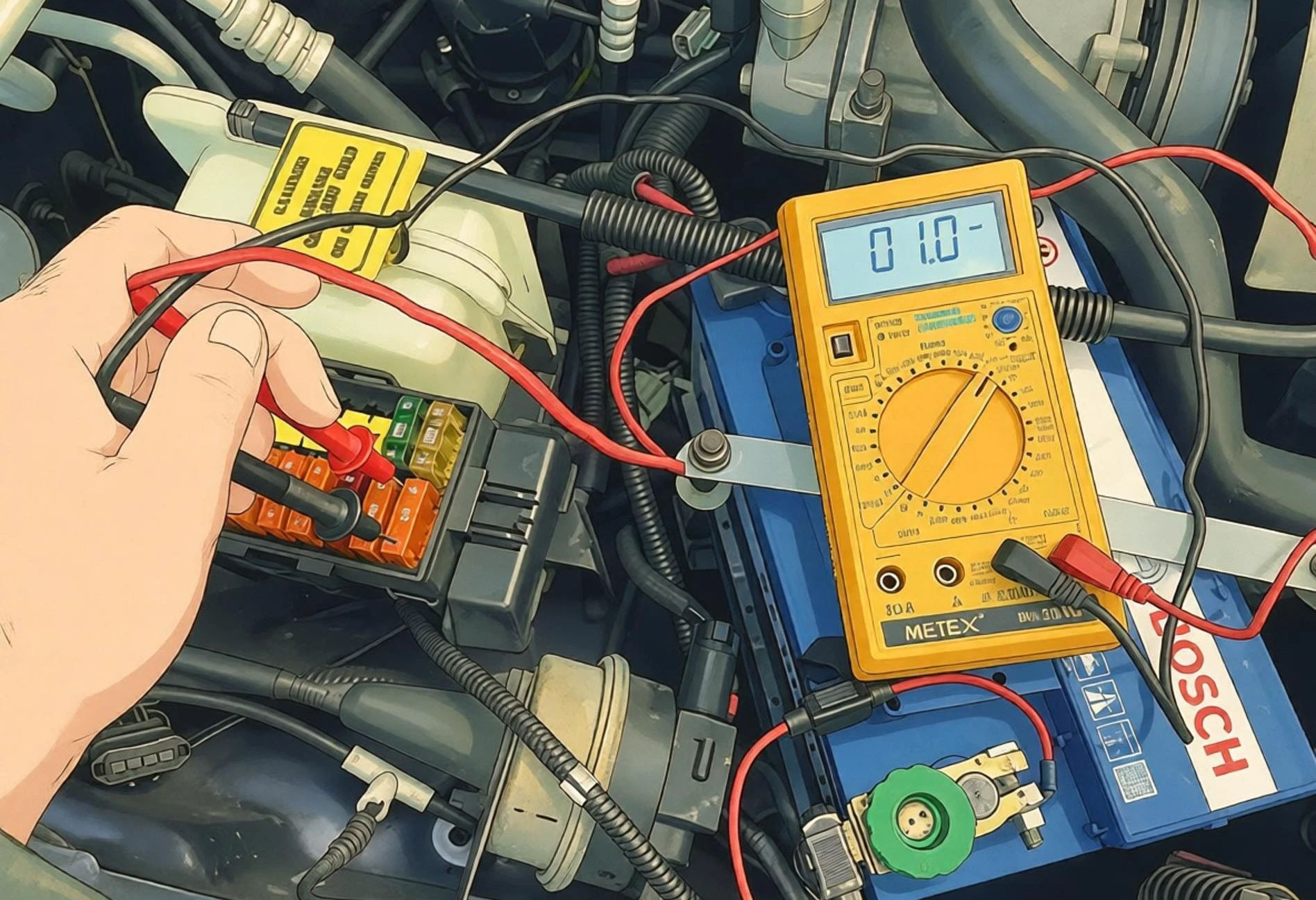
When diagnosing a car battery that constantly goes flat overnight, traditional fuse pulling often turns into a diagnostic nightmare. On modern vehicles equipped with CAN-bus computer networks, pulling a fuse instantly wakes up sleeping modules, causing current to spike and invalidating the test.
The Fuse Voltage Drop Method (using a Fuse Voltage Drop Chart) is the gold standard practiced by master diagnostic technicians: 100% zero fuse pulling, zero power interruption, and zero module wake-up. Armed with an ordinary digital multimeter, you can scan an entire fuse box in under two minutes and pinpoint the exact leaking circuit.
Series Navigation:
To measure total vehicle sleep current, see: Series Switch Guide DC Clamp Meter Guide
Core Principle: Ohm’s Law \(V = I \times R\)
Automotive blade fuses are not zero-resistance superconductors. The internal metal element has a small, known, and stable resistance (typically between 2mΩ and 30mΩ).
According to Ohm’s Law:
\[V = I \times R \quad \Longrightarrow \quad I = \frac{V}{R}\]- \(R\) (Fuse Internal Resistance): Fixed and known based on fuse type and amp rating.
- \(V\) (Voltage Drop): The tiny potential difference across the fuse terminals in millivolts (\(mV\)).
- \(I\) (Parasitic Current): The actual current flowing through the circuit in milliamps (\(mA\)).
Automotive blade fuses feature two exposed metal test points on their top edge. Measuring the millivolt difference (\(mV\)) across these two test points allows you to directly calculate the current without opening the circuit.
Required Tools
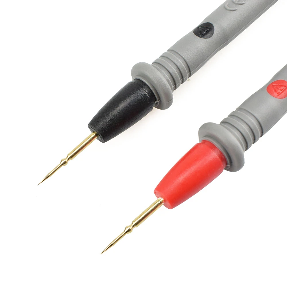
- Digital Multimeter (DMM): Set to the DC mV (millivolt) scale (resolution of 0.1 mV or 0.01 mV).
- Fine-Tipped Probes (Essential): Standard multimeter probes are too blunt to reach the recessed metal test pads. Use sharp 0.7mm–1.0mm needle probes to pierce through surface oxidation.
- Lookup Chart: The reference tables below.
Step-by-Step Measurement Procedure
Step 1: Latch Doors and Wait for Deep Sleep
- Turn off the ignition, switch off all accessories, and roll down all windows (preventing accidental lockouts).
- Open the access areas for all fuse boxes to be tested, and manually latch all door/hood/trunk latches using a screwdriver to simulate closed doors.
- Lock the vehicle using the key fob, and move keyless smart keys at least 5 meters (16 ft) away.
- Wait 15 to 45 minutes to ensure all body control modules (BCM, ECU, gateway) enter deep sleep mode.
Step 2: Multimeter Setup and Probing
- Connect the red probe to the V/Ω/mV jack and the black probe to COM.
- Turn the selector knob to DC mV.
- Firmly press the two sharp probe tips into the two exposed metal test points on top of the fuse, applying slight pressure to pierce any oxidation.
- Read the display:
0.0 mV: No current flow. The circuit is asleep; move directly to the next fuse.- Numeric reading (e.g.,
0.6 mV): Current is actively flowing through this fuse. Note the fuse type (Mini or Standard/ATO), amp rating, and mV reading.
Reading Negative Millivolts (e.g., -0.5 mV)?
Polarity merely reflects which side the red lead is touching. Fuses have no polarity; use the absolute value (0.5 mV) to read the chart.
Fuse Voltage Drop Reference Tables
Once you record a millivolt reading, reference the tables below to find the current draw in milliamps (mA):
1. Mini Blade Fuse (ATM) Voltage Drop Table (Unit: mA)
| Fuse Rating | Approx. Resistance | 0.2 mV | 0.4 mV | 0.6 mV | 0.8 mV | 1.0 mV | 1.5 mV | 2.0 mV |
|---|---|---|---|---|---|---|---|---|
| 5A (Tan) | ~15.2 mΩ | 13 mA | 26 mA | 39 mA | 53 mA | 66 mA | 99 mA | 132 mA |
| 7.5A (Brown) | ~10.1 mΩ | 20 mA | 40 mA | 59 mA | 79 mA | 99 mA | 149 mA | 198 mA |
| 10A (Red) | ~7.1 mΩ | 28 mA | 56 mA | 85 mA | 113 mA | 141 mA | 211 mA | 282 mA |
| 15A (Blue) | ~4.6 mΩ | 43 mA | 87 mA | 130 mA | 174 mA | 217 mA | 326 mA | 435 mA |
| 20A (Yellow) | ~3.3 mΩ | 61 mA | 121 mA | 182 mA | 242 mA | 303 mA | 455 mA | 606 mA |
| 25A (Clear/White) | ~2.5 mΩ | 80 mA | 160 mA | 240 mA | 320 mA | 400 mA | 600 mA | 800 mA |
| 30A (Green) | ~2.0 mΩ | 100 mA | 200 mA | 300 mA | 400 mA | 500 mA | 750 mA | 1000 mA |
2. Standard Blade Fuse (ATO / ATC) Voltage Drop Table (Unit: mA)
| Fuse Rating | Approx. Resistance | 0.2 mV | 0.4 mV | 0.6 mV | 0.8 mV | 1.0 mV | 1.5 mV | 2.0 mV |
|---|---|---|---|---|---|---|---|---|
| 5A (Tan) | ~17.8 mΩ | 11 mA | 22 mA | 34 mA | 45 mA | 56 mA | 84 mA | 112 mA |
| 7.5A (Brown) | ~10.9 mΩ | 18 mA | 37 mA | 55 mA | 73 mA | 92 mA | 138 mA | 183 mA |
| 10A (Red) | ~7.4 mΩ | 27 mA | 54 mA | 81 mA | 108 mA | 135 mA | 203 mA | 270 mA |
| 15A (Blue) | ~4.8 mΩ | 42 mA | 83 mA | 125 mA | 167 mA | 208 mA | 313 mA | 417 mA |
| 20A (Yellow) | ~3.4 mΩ | 59 mA | 118 mA | 176 mA | 235 mA | 294 mA | 441 mA | 588 mA |
| 25A (Clear/White) | ~2.6 mΩ | 77 mA | 154 mA | 231 mA | 308 mA | 385 mA | 577 mA | 769 mA |
| 30A (Green) | ~2.1 mΩ | 95 mA | 190 mA | 286 mA | 381 mA | 476 mA | 714 mA | 952 mA |
Quick Mental Math Rule (Common Mini 10A Fuse):
Every 0.1 mV drop equals approximately 14 mA of parasitic current. A reading of0.5 mVrepresents \(0.5 \times 14 = 70\text{ mA}\).
Verifying and Isolating the Faulty Component
Once you identify a fuse with an active voltage drop, do not pull the fuse:
- Check Fuse Allocation: Consult the owner’s manual or fuse box diagram to identify which devices are fed by this fuse (e.g., aftermarket radio, dash cam hardwire kit, body module, dome lights).
- Disconnect the Suspect Device: Unplug the power harness at the component itself (not at the fuse box).
- Re-test the Fuse Voltage Drop: If the reading instantly drops from
1.2 mVto0.0 mV, you have confirmed the culprit!
Diagnostic Workflow Summary
- Step 1 (Total Current Check): Clamp the negative battery cable with a DC clamp meter for 30 seconds to confirm if abnormal drain exists (< 50mA is normal).
- Step 2 (Alternator Check): Clamp the alternator B+ output cable to rule out internal rectifier diode leakage.
- Step 3 (Pinpoint the Circuit): Probe fuses with a multimeter on DC mV using the voltage drop chart to pinpoint the culprit circuit in 2 minutes without waking the vehicle!