Technical Notes: Principles of Wheel Balancers and Tire Uniformity
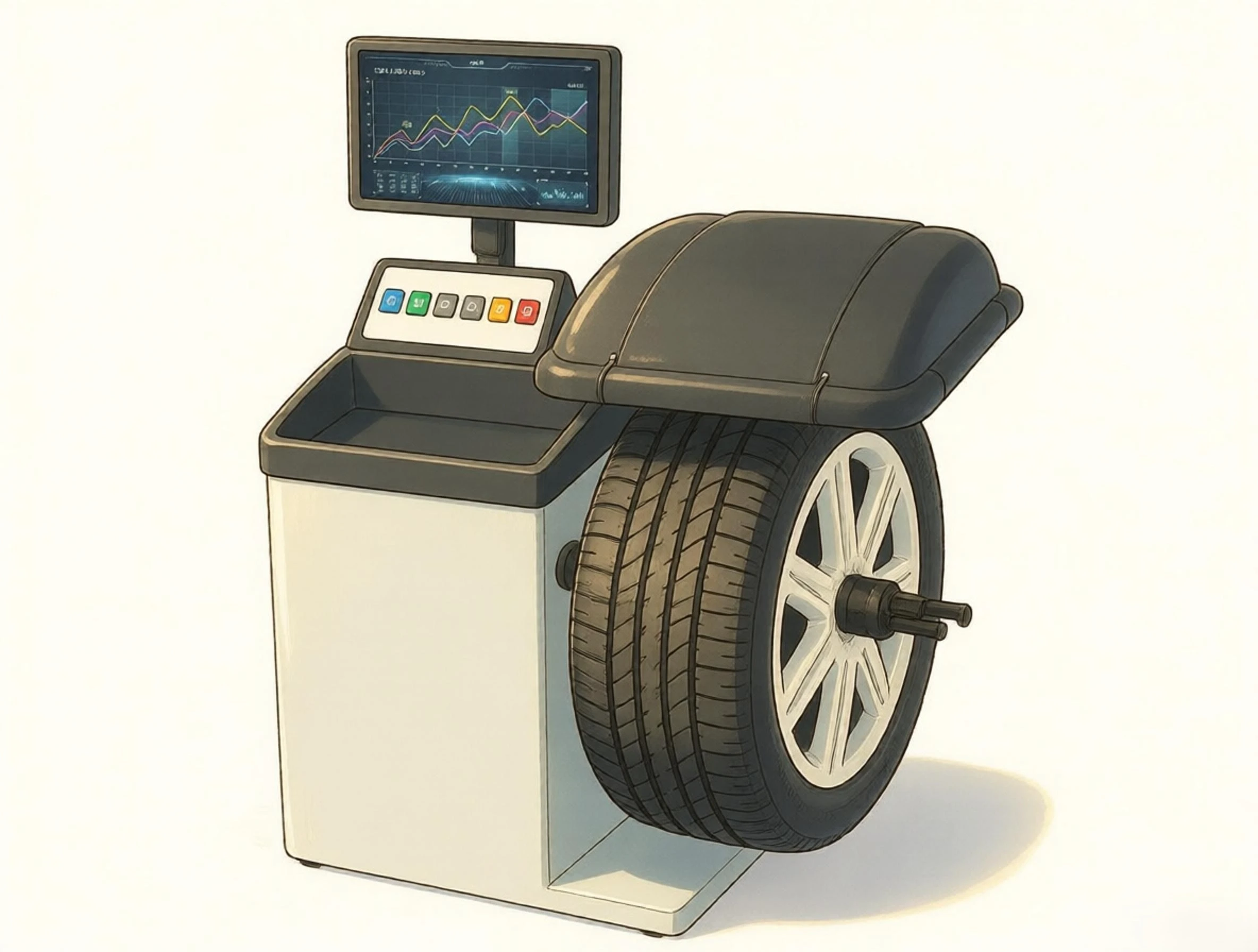
Many drivers encounter this frustrating paradox: The wheels are balanced to a perfect 0g / 0g on the balancer, yet the steering wheel shakes at 110 km/h; the wheel alignment is dead-on, yet the car stubbornly pulls to one side when you let go of the wheel. To cure high-speed chassis disturbances, one must look beyond basic weight distribution and understand the physics of Tire Uniformity (U/F).
1. Operating Principles of the Wheel Balancer
As a wheel rotates at high speeds, even minor mass asymmetries are exponentially magnified by centrifugal force. The balancer is designed to isolate and nullify these dynamic disturbances.
- Countering Two Types of Imbalance:
- Static Imbalance (Vertical Hop): The center of mass is offset from the rotational axis. The resulting radial centrifugal force pulls the wheel outward, causing vertical hopping.
- Dynamic Imbalance (Side-to-Side Wobble): Non-symmetrical mass distribution across the inner and outer planes creates a rotating force couple, causing the wheel assembly to shimmy and wobble about the steering axis.
- Sensing and Two-Plane Resolution:
- Piezoelectric Sensors: High-stiffness quartz transducers on both spindle bearings register micro-meter (\(\mu\text{m}\)) dynamic deflections, measuring the magnitude of alternating forces.
- Optical Rotary Encoder: Tracks shaft angle with sub-degree accuracy (\(< 0.5^\circ\)) to pin down the exact angular phase of the unbalance.
- Two-Plane Algorithm: Simultaneously solves force balance (\(\sum \vec{F} = 0\)) and moment balance (\(\sum \vec{M} = 0\)) to compute the precise correction weight (grams) and clock position on both inner and outer rim planes.
2. What Do the Red and Yellow Dots on a Tire Mean?
The colored dots on the sidewall of brand-new tires are quality marks from factory uniformity testing, serving as the first line of defense during mounting:
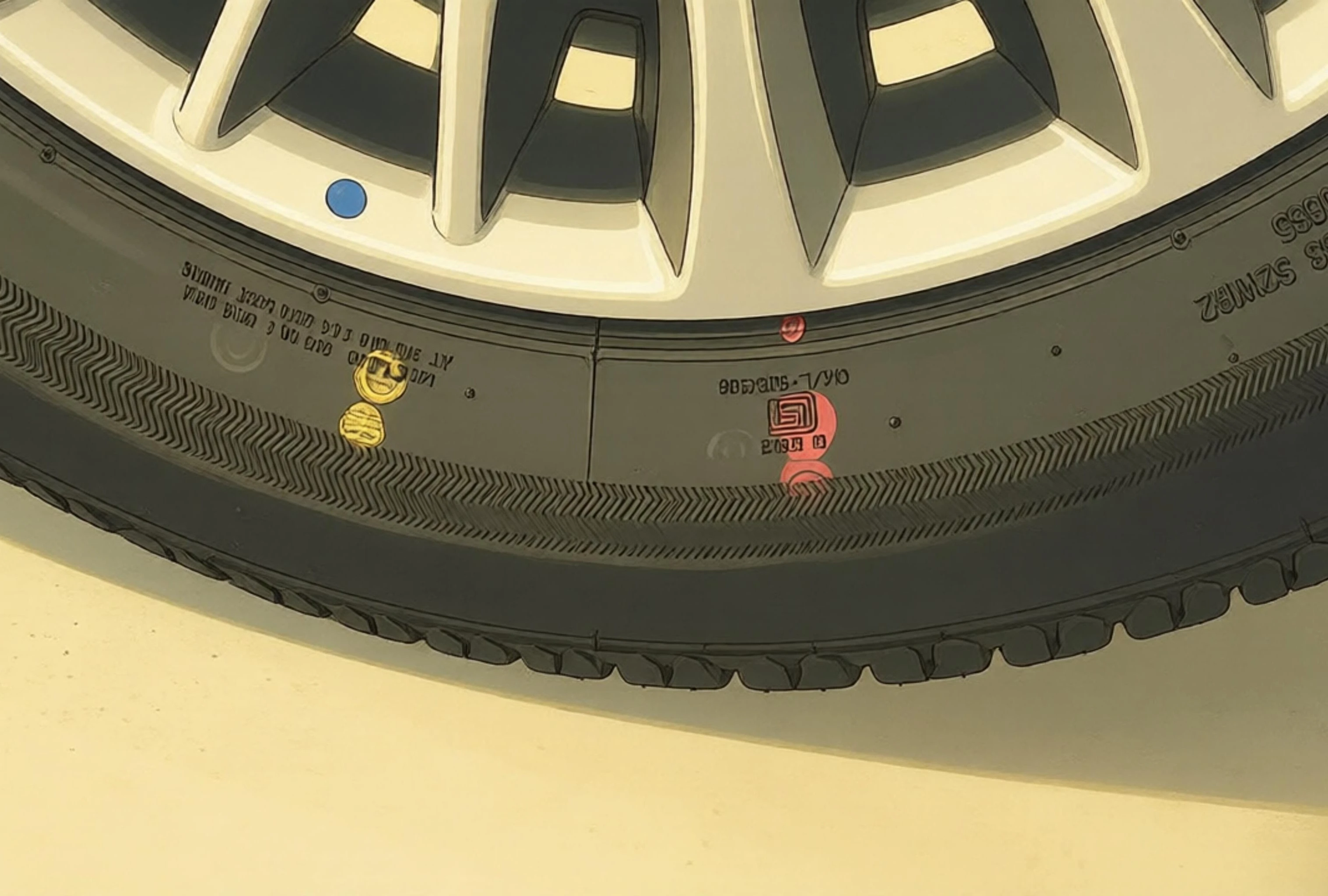
- Red Dot (RFV 1H / Radial Runout High Spot):
- Specifically marks the peak of the first harmonic radial force variation (RFV 1H)—the once-per-revolution stiffness peak that most easily triggers vehicle resonance.
- Mounting Rule: Prioritize aligning the red dot with the wheel’s radial runout minimum dimple (rim low spot). The geometric dip in the wheel cancels out the structural high spot of the tire.
- Yellow Dot (Lightest Weight Point):
- Marks the lightest point around the circumference of the tire.
- Mounting Rule: When the rim has no low-spot marking, align the yellow dot with the valve stem (the heaviest point on the rim) to minimize the amount of clip-on or adhesive weights needed.
- Which Takes Precedence When Red and Yellow Conflict?
- The Red Dot always takes priority. Mass unbalance (yellow dot) can easily be neutralized with lead/zinc weights on a balancer, but structural stiffness variation (red dot) cannot be fixed with weights once mounted incorrectly.
3. Why 0g Balance Still Shakes: RFV, LFV, and True Solutions
The fundamental limitation of standard balancers is that the tire spins in the air without any load. They only solve weight distribution, leaving RFV and LFV completely untouched.
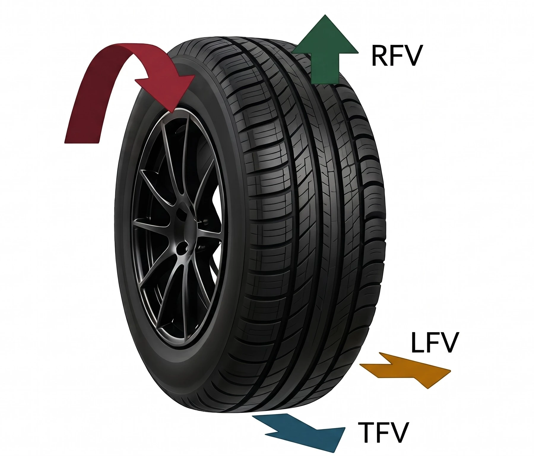
- RFV & RFV 1H (Radial Force Variation, Lower is Better):
- Cause: Uneven ply splices or structural stiffness variations in the sidewall. In the air, the tire spins round; but under vehicle weight (~500 kg), the stiffer section refuses to compress, acting like a cam that bounces the chassis vertically. Laser optical sensors measure RRO (Radial Runout, mm) to distinguish between physical out-of-roundness and internal stiffness spikes.
- LFV, CONG, and PLY (Lateral Force Variation & Conicity, Lower / Near Zero is Better):
- CONG (Conicity): Caused by a conical shape (left-right diameter mismatch). Rolling behaves like a paper cup, pulling toward the smaller side. Flipping the tire on the rim reverses the pull direction (can be neutralized by flipping or swapping).
- PLY (Ply Steer): Lateral shear generated when angled steel belt cords flatten under vertical load. Flipping the tire does NOT reverse the pull direction (inherent structural bias).
- Total Lateral Push: Governed by the vector sum:
\(\text{Total Lateral Force} = \text{CONG} + \text{PLY}\)
-
Example: A tire leaves the factory with \(CONG = +80\text{ N}\) (pushing right) and \(PLY = +40\text{ N}\) (pushing right):
\[\text{Factory Net Push} = (+80\text{ N}) + (+40\text{ N}) = +120\text{ N} \quad (\text{noticeable pull to the right})\]If the technician dismounts and flips the tire on the rim, CONG reverses to \(-80\text{ N}\), but PLY stays at \(+40\text{ N}\):
\[\text{Flipped Net Push} = (-80\text{ N}) + (+40\text{ N}) = -40\text{ N} \quad (\text{push drastically reduced, mild left drift})\]The steering pull sensation is noticeably relieved!
-
- RAT (Residual Aligning Torque): The lateral force offset generates a self-aligning torque around the kingpin, pulling the steering wheel off-center or causing asymmetrical return-to-center feel.
How to Truly Eliminate RFV and Lateral Pulling
- Road Force Balancer Diagnosis:
- Machines like the Hunter Road Force series press an automated load roller against the tire with ~500–600 kg of force, measuring real-world dynamic RFV and lateral force.
- ForceMatch Phase Optimization (Canceling RFV):
- The machine scans the rim’s runout low spot and calculates the tire’s RFV 1H stiff spot.
- The technician breaks the beads and rotates the tire on the wheel (e.g., 180°), using the rim’s geometric dip to absorb the tire’s stiff peak, bringing physical vibration to near zero.
- Tire Placement Optimization (Canceling Lateral Push & Shimmy):
- Based on measured lateral forces (CONG + PLY), front tires are swapped side-to-side to cancel net pulling forces. Tires with the lowest LFV/RFV variation are placed on the front steer axle.
4. Five Key Signs of Quality Balancing Service
- Collet & Cone Condition: A dirty, worn, or dented mounting cone can induce 0.1 mm of off-center play, creating 10–15g of phantom unbalance.
- Surface Cleaning: Old adhesive weights and tape residue must be stripped completely; tire stones and inner moisture must be removed.
- Dot Alignment: Tires should be deliberately matched according to red/yellow dot protocols, rather than haphazardly mounted and weighed down with excessive lead.
- Double-Check Spin: The technician should always lower the hood and re-spin the finished wheel to verify a confirmed “0g / 0g” readout.
- Road Force for Stubborn Cases: If a vehicle vibrates at 110–120 km/h despite 0g balance, request a load roller ForceMatch service.
Summary
The complete chain of high-speed stability:
- Standard Balancers handle free-spinning mass, canceling hop and wobble force couples with counterweights.
- Red & Yellow Dots provide the first line of defense during assembly to minimize initial runout and weight usage.
- RFV & LFV are loaded stiffness and geometric forces that lead weights cannot fix—they require Road Force measurement and ForceMatch phase optimization to conquer.